3 Element All Active High Impedance Receiving Array
![]() For 160, 80,
and 40 meters
For 160, 80,
and 40 meters![]()
And the tiny back yard!!![]()
K7TJRcopyright
See www.hizantennas.com for array components and systems
It was with great persuasion from my good friend Ron, KB7ZR that I designed the controller that could implement a receiving array with 3 High impedance elements. He kept telling me he did not have enough room for 4 elements in his back yard to implement a 4-square and what could I do to help him with low-band receiving. I drew out a schematic sketch of a three element array and the first thing I knew Ron had one built. Having looked carefully at this antennas characteristics, it became pretty clear that this antenna had the potential of working slightly better than the infamous K9AY loop antenna. It showed slightly better RDF and a great front to back ratio. And in addition could be switched in 6 different directions. The challenge almost certainly would be maintaining antenna amplitude and phase stability in such a small footprint. As it turned out with careful study this antenna was reasonably insensitive to the amplitude and phase stability compared to a 4 element array. Ron started relating some pretty decent performance. In fact he said he was replacing his K9AY array. It would be an excellent idea to read the K7TJR 8 element array page before the rest of this page in that there is a lot more discussion there behind the principles of the Hi-Z amps and array techniques. This three element array is laid out and physically described as follows.
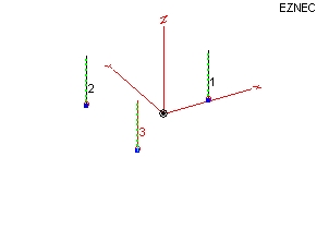
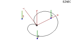
This arrangement sets up an element every 120 degrees around a circle. This is an equilateral triangle. The radius of the circle is 0.58 times the length of one side. The height from elements 2,3 to element 1 is .87 times the length of one side. The actual center of the triangle occurs at .29 times the side length from elements 2 and 3 toward element 1. I know, I know this is hard to describe. Here is a diagram.
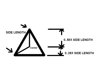
When cutting the interconnect wires for this array, one should use 0.58 times the side length and then add 2 feet or so for a little connection room to the center. It has been pointed out that if you are installing an array over brushy ground one should add even more extra length..
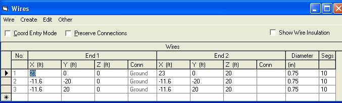
Here is the Eznec wires information for the model.
This array produces a basic Cardiod pattern by feeding two elements combined against one element single. This requires an attenuation of the two elements that are combined by 1/2 voltage or 6 dB. The really interesting thing about this array is that you can use it in 6 directions by selecting and inverting phase relationships. On the surface it would seem you could only point toward the leading element but by inverting the phases you can point toward the element pair as well. By using a form of time delay phasing this array will provide the same pattern over a wide bandwidth. The Array gets a bit sensitive on a 40 foot side dimension on 160 meters and will work very well on 80. Raising the side dimension to 50 or 60 feet will enhance the performance on 160 meters and the RDF will begin to drop on 40 meters. Suffice to say the array will suffer very little degradation from sizing and will be generally a very good performer across three bands. Beyond 60 feet side dimension I recommend an Eznec analysis based on personal performance desires. The controller has been designed to provide very accurate phase tracking and will provide a good 30 dB front to back ratio on 160 meters in a 40 foot side dimension triangle.
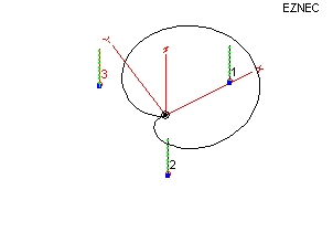
This makes for a little more complicated switching, however it is fairly straight forward to implement with relays. The following picture shows the overlap between two switched directions with the array.
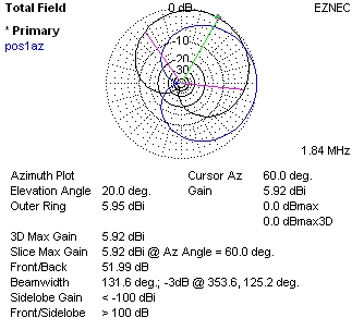
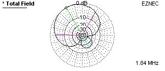
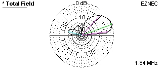
The notch off the back of this array has proven to be very useful in eliminating interference as it is somewhat steer able. One can still pick up the main signal with the wide front lobe while moving the notch off the back for interference reduction.
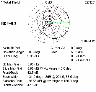
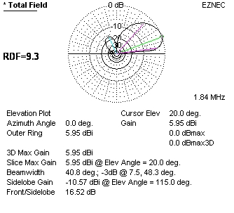
The above plots are taken with the phasing adjusted for a maximum front to back ratio. By adjusting the phasing one can get the low angle RDF up to 9.8 dB as seen below. Equivalent K9AY RDF is 7.2 dB at 20 degrees elevation. Notice that the high angle back lobe can be moved up and down for local interference reduction by phasing selection.
This array uses the 20 foot elements as described in the 8 element array pages. They are basically an insulated element with the K7TJR high impedance amplifier at the base of each element to drive the controller circuitry.
![]()
![]()
All web content copyright K7TJR